
Un tastatore CNC a 5 assi può rendere più ripetibili l'allestimento del pezzo e i controlli in macchina, ma la pianificazione del ciclo di tastatura richiede molto più che la semplice aggiunta di un movimento rotatorio a una routine convenzionale a 3 assi. La rotazione modifica il raggio d'azione fisico del mandrino, del corpo della sonda, dello stilo, del portautensili, del sistema di serraggio del pezzo e degli assi della macchina. Può inoltre modificare la direzione in cui lo stilo entra in contatto con l'elemento da misurare.
Ecco perché un ciclo che sembra corretto in uno screenshot del CAM potrebbe comunque risultare inadatto sulla macchina. La domanda pratica non è solo: “Il tastatore può toccare questa caratteristica?”, ma anche: “L’intero gruppo di sonda è in grado di avvicinarsi, toccare, ritirarsi e spostarsi al punto successivo senza entrare in una condizione di rischio di collisione?”.”
La presente guida offre a operatori di macchine utensili, ingegneri di processo e responsabili acquisti un metodo di pianificazione per i cicli CNC a 5 assi con sonda di misura. È applicabile sia che l'obiettivo sia impostazione di un offset di lavoro, controllando una caratteristica nel sistema di serraggio originale o verificando la posizione di un dispositivo di fissaggio. I cicli esatti, le posizioni di sicurezza, gli avanzamenti, le interfacce e i limiti devono sempre essere approvati per la macchina, il controllore, il sistema di sonda, il portasonda, lo stilo e il sistema di serraggio specifici.
Indice dei contenuti
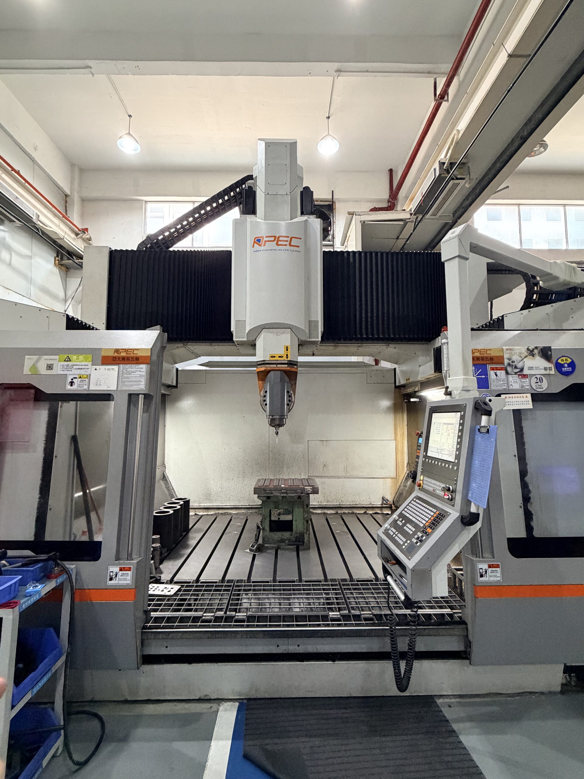
Perché la progettazione con sonda di misura CNC a 5 assi richiede un metodo specifico
Su un centro di lavoro verticale a 3 assi, la sonda si avvicina normalmente a un elemento partendo da un orientamento consolidato del mandrino. Una macchina a 5 assi aggiunge la rotazione della tavola, quella della testa o entrambe. Questi movimenti possono migliorare l’accessibilità, ma sollevano ulteriori interrogativi:
- Il corpo della sonda non interferisce con il dispositivo di fissaggio, i morsetti, la tavola rotante, il supporto verticale e il pezzo all’angolo selezionato?
- La direzione di contatto scelta è normale alla superficie o adeguata alla caratteristica da misurare?
- Lo stilo raggiunge la superficie senza che il corpo della sonda o la punta del mandrino diventino l’oggetto più vicino al pezzo?
- I percorsi di avvicinamento e di rientro rimangono liberi anche dopo che il sistema di controllo ha applicato il movimento dell'asse rotante ed eventuali trasformazioni di coordinate?
- L'opzione di sondaggio fornita dal produttore della macchina supporta la routine di misurazione prevista (su piano inclinato, cinematica o a 5 assi)?
L'ultima domanda è importante. Una sonda invia un segnale di attivazione; il CNC, integrazione delle macchine, e il software di sondaggio determina come viene interpretato il segnale e quale movimento viene eseguito successivamente. Non date per scontato che un sistema di sondaggio offra una determinata funzione a 5 assi solo perché un sistema simile la offre altrove.
Inizia dalla scelta della misura, non dal movimento della sonda
Prima di definire i punti di programmazione, occorre stabilire quale decisione sarà supportata dal risultato. In questo modo la procedura rimane proporzionata al rischio.
Ad esempio:
| Obiettivo della misurazione | Risultato utile | Prossimo passo tipico |
|---|---|---|
| Individuare un pezzo grezzo o un supporto | Risultato dell'offset o dell'allineamento | Proseguire solo se il risultato rientra in un intervallo consentito |
| Confermare un elemento di riferimento prima di terminare | Confronto tra posizioni o piani | Sospendere, correggere o procedere secondo il piano di controllo |
| Verificare una caratteristica fondamentale nel sistema di serraggio originale | Valore registrato o risultato “superato/non superato” | Attenersi al piano di reazione approvato |
| Verificare l'asse rotante o la geometria della macchina | Dati di verifica specifici per macchina | Attenersi alle istruzioni del costruttore della macchina o alle procedure di manutenzione qualificate |
Si eviti di consentire che una misura modifichi automaticamente un offset, a meno che la caratteristica, la tolleranza, i limiti, l'offset e l'azione di recupero non siano stati espressamente qualificati. Un trigger valido non dimostra di per sé che il valore misurato sia idoneo alla correzione automatica.
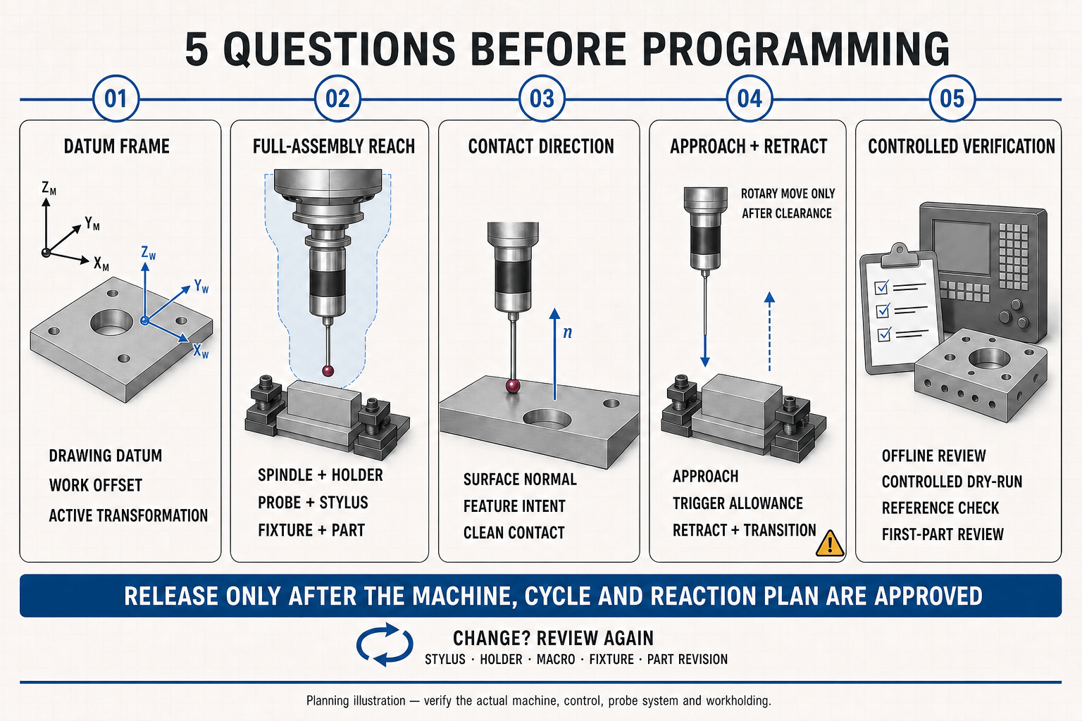
Le cinque domande a cui rispondere prima di iniziare a programmare
1. Qual è il sistema di riferimento in questo orientamento?
Identificare separatamente il punto di riferimento del disegno, il punto di riferimento di impostazione e il sistema di coordinate di lavoro CNC. Dopo un movimento rotatorio, verificare quale sistema di coordinate utilizzi il ciclo e se sia attivo un piano di lavoro inclinato, una trasformazione o un sistema di coordinate della macchina. Un punto che sembra corretto in un sistema di coordinate può risultare errato in un altro.
Annotare quanto segue nel documento di configurazione:
- offset di lavoro attivo;
- orientamento A/B/C imposto o posizione indicizzata;
- trasformazione attiva o funzione del piano inclinato;
- indicare il valore nominale e l'intervallo di risultati ammesso;
- posizioni di avvicinamento e di ritirata in sicurezza; e
- l'azione da intraprendere in caso di risultato entro tolleranza, di avviso o fuori tolleranza.
2. L'intero gruppo può raggiungere l'elemento?
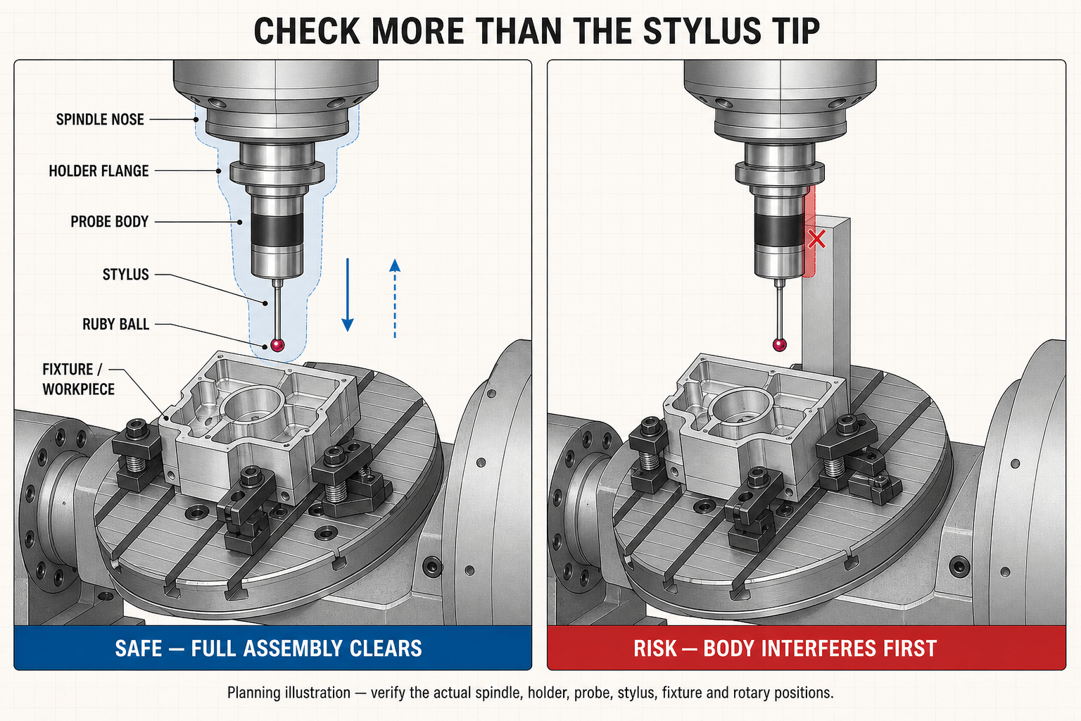
Check the clearance envelope of the spindle nose, holder, probe body, stylus stem, and ball—not just the ball. Long styli can improve reach but can also make the assembly less stiff and more vulnerable to collision. A short, direct stylus is generally easier to protect and qualify when it can reach the feature.
Use the actual holder and stylus geometry in the digital setup when available. If the digital model is incomplete, make a controlled dry-run with the spindle stopped, reduced rapid override, and an operator able to stop the machine. A simulation is a planning aid, not proof that the physical machine is clear.
3. Is the contact direction meaningful?
The touch direction affects what the stylus is actually sensing. For a planar face, a near-normal contact direction is usually the clearest way to evaluate that face. For bores, bosses, and side walls, the strategy should match the geometry being reported. Probe in the direction needed by the approved routine, not merely the direction that is easiest to reach.
Consider coolant films, burrs, chips, and surface condition too. These can influence the practical reliability of a contact event. Clean the relevant surface and choose a conservative approach that is suitable for the approved cycle.
4. Is there clearance for both approach and retreat?
Every probing point needs more than one collision check. Verify:
- the move from the tool-change or previous safe position to the pre-approach position;
- the probing approach;
- the overtravel allowed after trigger, as defined by the cycle;
- the retract; and
- the move to the next feature or the next rotary position.
An indexed table can bring a clamp into the path after an otherwise safe move. On machines with a swivelling head, the head, probe, and fixture relationship may change rapidly during a rotary move. Put rotary moves at known safe positions and avoid relying on visual judgment alone.
5. How will the routine prove that it is ready?
Before measuring production parts, use a staged verification:
- Offline review: Check the correct probe assembly, stylus, holder, part, fixture, and machine limits in the planning system.
- Empty-machine check: Confirm communication, probe selection, and intended program state without a production part at risk.
- Controlled dry-run: Use safe height, reduced overrides, and single-block or equivalent control where appropriate.
- Reference-artifact check: Where the qualified process calls for it, verify the routine on an approved artifact or known feature.
- First-part review: Compare results with the process plan and independently verify any unexpected result before changing production data.
This sequence is especially important after changes to the stylus, holder, probe battery or transmission arrangement, machine parameters, probing macro, fixture, or part revision.
Lista di controllo pre-volo per sonda di misura CNC a 5 assi
Use this checklist before releasing a new or altered cycle:
- [ ] The measurement purpose and reaction plan are documented.
- [ ] The drawing datum, work offset, and active transformation are understood.
- [ ] The actual probe, holder, and stylus match the programmed assembly.
- [ ] The probe assembly and feature are accessible at every commanded orientation.
- [ ] Body, holder, spindle-nose, clamp, table, and part clearances have been considered.
- [ ] Each approach, trigger allowance, retract, and transition has a safe path.
- [ ] Probe qualification/calibration is current for the installed assembly and approved procedure.
- [ ] The control and machine integration support the intended 5-axis routine.
- [ ] The program handles a no-trigger, unexpected trigger, or out-of-range result safely.
- [ ] The first run has a documented controlled-verification plan.
Errori comuni nella pianificazione
Measuring from an unreviewed tilted coordinate frame
The operator may see the correct feature on screen while the program uses a different active plane or work offset. Keep the intended coordinate frame explicit in both the program and setup sheet, and review it after every manual recovery or restart.
Treating stylus length as a simple reach problem
A longer stylus may clear a wall, but it changes the mechanical assembly and may demand a different qualification method or more conservative process. Choose the shortest geometry that safely reaches the feature and verify it according to the supplier’s and process owner’s instructions.
Rotating before retracting to a proven safe position
The correct move sequence is machine- and fixture-specific, but the principle is universal: establish clearance before changing the relationship between the probe and the workholding. Never assume a rotary move is safe because the prior probe point was safe.
Using the same cycle for setup and final acceptance
A setup check may be designed to locate stock or a fixture quickly. Final acceptance may require a different datum, sampling plan, temperature condition, surface preparation, or independent verification. State the purpose of each routine so operators do not use a convenient cycle outside its approval.
Correcting offsets from a single unexplained result
Before any correction, check probe qualification status, part seating, clamps, chips, burrs, tool condition, program state, coordinate frame, and the feature itself. If the result remains unexpected, follow the control plan rather than masking the condition with an offset change.
Cosa dovrebbero chiedere gli acquirenti riguardo a un trasduttore di misura CNC a 5 assi
International buyers should evaluate the complete application, rather than requesting only a probe diameter or transmission type. Useful questions for the machine builder, integration partner, or probe supplier include:
- Which CNC controls and probing options are supported for this machine configuration?
- Is the machine head/table arrangement compatible with the intended workpiece access and probe transmission method?
- Which probe holders, shanks, styli, and spare parts are available for the spindle interface?
- What documentation is supplied for wiring or receiver placement, macros, qualification, and fault handling?
- Who is responsible for commissioning the probe cycles and validating safe clearances?
- What local support is available for installation, software integration, and service?
Qidu’s public touch-probe range includes cabled, infrared optical, radio, and modular probe categories. The right configuration depends on the machine, control, spindle interface, working envelope, intended routine, and integration details. Confirm current product documentation, drawings, interface requirements, and availability with Qidu before specifying or ordering.
Un semplice flusso di lavoro di rilascio per una routine di sondaggio a 5 assi
- Define the feature, datum, decision, and reaction plan.
- Select the smallest practical probe/stylus assembly that can reach it.
- Review the complete physical envelope at every orientation.
- Program only with the controller and machine options actually installed.
- Qualify the assembly using the approved procedure.
- Prove the paths in a controlled run.
- Record the released program revision, assembly, fixture, and verification result.
- Re-run the review when any of those conditions changes.
The value of this workflow is not that it makes every 5-axis routine identical. It makes the assumptions visible before a probe, fixture, part, or spindle is put at risk.
Conclusione
5-axis CNC probing can extend access to important features in the original clamping, but its reliability depends on planning the full motion and measurement context. Start with the decision the result must support; then verify the datum frame, assembly geometry, contact direction, clearance for every segment, and a controlled release process.
For a new application, have the machine builder, control specialist, and qualified process owner review the cycle before production. This article is a planning guide, not a substitute for the machine manual, probe documentation, risk assessment, or technical validation. Search visibility, rich-result appearance, indexing, and ranking cannot be guaranteed.
