
Installing a CNC probe is not especially difficult. Getting it to measure reliably is where the real work begins.
目次
A probe may power on, communicate with the receiver, and trigger normally, yet still give disappointing results. Usually, the probe itself is not defective. The cause is more ordinary: the stylus is not running on the spindle centerline, the calibration reference was dirty, the machine was still warming up, or the final tightening moved the probe body by a few microns.
This guide covers the complete on-site process for a spindle-mounted CNC touch probe: installation, signal testing, stylus centering, calibration, verification, and troubleshooting.
Exact screw positions, torque values, M-codes, and calibration cycles vary by model. Keep the product manual beside the machine. The method below explains the working process; the manufacturer’s manual provides the final numbers.
What Does “Adjusting CNC Probe Accuracy” Actually Mean?
There is rarely a single accuracy adjustment on a CNC probe.
Reliable measurement depends on four separate jobs:
- Mount the probe securely.
- Align the stylus with the spindle centerline.
- Calibrate the probe length, XY offset, and effective stylus radius.
- Verify the complete system using a known reference.
These jobs are related, but they are not interchangeable.
Mechanical centering reduces stylus runout. Calibration teaches the CNC control where the probe actually triggers. Verification tells you whether the probe, machine, software, and reference setup agree with one another.
Trying to correct a calibration problem by turning the centering screws is a good way to lose an afternoon without fixing the real issue.
What to Prepare Before Installation CNC Probe
Before opening the machine door, gather everything you will need.
This normally includes:
- について probe body, shank, スタイラス, batteries, receiver, and interface
- The correct probing macro package for the CNC control
- A clean dial test indicator
- A rigid magnetic or mechanical indicator stand
- Clean hex keys
- A small torque wrench
- Lint-free wipes and suitable cleaning fluid
- A simple test program with conservative movements
You will also need two reliable calibration references:
- A known flat surface or length standard for Z calibration
- A calibrated ring gauge or accurately known bore for XY and stylus-radius calibration
Before beginning, confirm that the shank fits the spindle, the receiver is connected to the correct machine input, and the probe’s activation method is supported.
Check that the correct probing macros are installed for the actual CNC control. Machine builders sometimes use custom M-codes, variables, or protected-positioning routines, so never assume that a program taken from another machine will work unchanged.
Step 1: Start With a Clean, Warm Machine
Stop the spindle and follow the site’s normal setup or lockout procedure before working around the spindle, toolchanger, or receiver.
Then think about temperature.
A probe can be centered perfectly on a cold machine and appear to lose accuracy after the spindle, machine casting, and axes warm up. If the probe will normally be used during production, run the machine’s usual warm-up cycle before completing the final calibration.
Clean the following surfaces carefully:
- The spindle taper
- The probe shank
- The stylus threads
- The indicator contact area
- The ring gauge or calibration bore
- The Z reference surface
A small chip trapped between the shank and spindle can create more error than the probe mechanism itself.
Do not rush this stage. Every measurement that follows depends on a stable, clean mechanical connection.
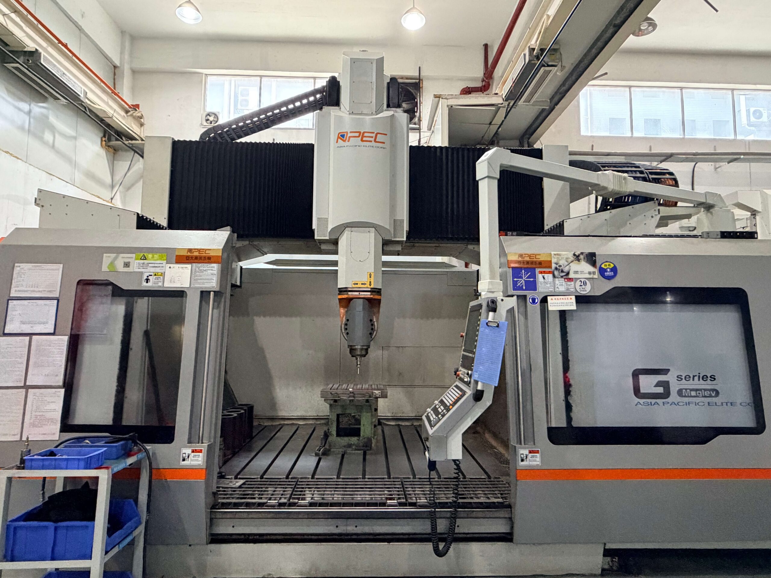
Step 2: Assemble the CNC Probe Without Forcing It
Install the batteries in the correct orientation and inspect the probe’s status indicators.
Configure the communication channel, switch-on method, timeout, and filtering according to the machine and receiver. Avoid changing several settings at once. When something fails later, it is much easier to troubleshoot when you know which setting was changed.
Fit the stylus using the tool and tightening torque recommended for that probe.
Do not grip the ruby ball with pliers. Do not apply thread-locking compound unless the manufacturer specifically permits it.
Use the shortest stylus that can reach the required features safely. A long stylus may be necessary for a deep pocket or difficult fixture, but it will generally be easier to bend, vibrate, or disturb during measurement.
When a weak link is required, use the correct version for the stylus material and application. Its purpose is to protect the probe from excessive overtravel. It is not intended to improve measuring accuracy.
Step 3: Mount the CNC Probe to the Shank
Most spindle probes use one set of screws to secure the body to the shank and another set to adjust the probe on center.
Begin with the centering screws loose enough to permit adjustment. Seat the probe evenly against the shank and tighten the main mounting screws only to the preliminary value stated in the manual.
The assembly needs to be secure enough that it does not sag, but not so tight that the centering screws can no longer move the body predictably.
Do not attempt to center the probe by tapping the body with a hammer, screwdriver handle, or plastic tool.
Tapping may appear quicker, but it makes the final position difficult to control and may damage the internal mechanism. Renishaw’s OMP60 installation guide, for example, specifically warns users not to hit or tap the probe during its on-center adjustment. ([Renishaw][1])
Step 4: Test the Signal Before Adjusting Runout
Before spending time on fine mechanical adjustment, make sure the complete signal chain works.
Load the probe into the spindle and activate it using the machine’s normal command.
Confirm that:
- The probe switches on correctly
- The receiver recognizes the probe
- A gentle stylus deflection changes the probe status
- The CNC skip input responds
- No low-battery warning is present
- The probe does not trigger randomly while stationary
- The probe switches off using the expected command or timeout
For an optical probe, test communication across the intended machine volume.
A probe may communicate normally near the receiver but lose line of sight behind a rotary table, large fixture, or workpiece. Test the actual positions in which probing will occur.
For a radio probe, confirm that it is paired correctly and check for intermittent communication near the machine’s travel limits.
Perform the first protected moves in single block with the feed and rapid overrides reduced. The first automatic move is not the right moment to discover that the skip input has been wired incorrectly.
Step 5: Adjust the Stylus Runout
This is the operation most people mean when they talk about “adjusting probe accuracy.”
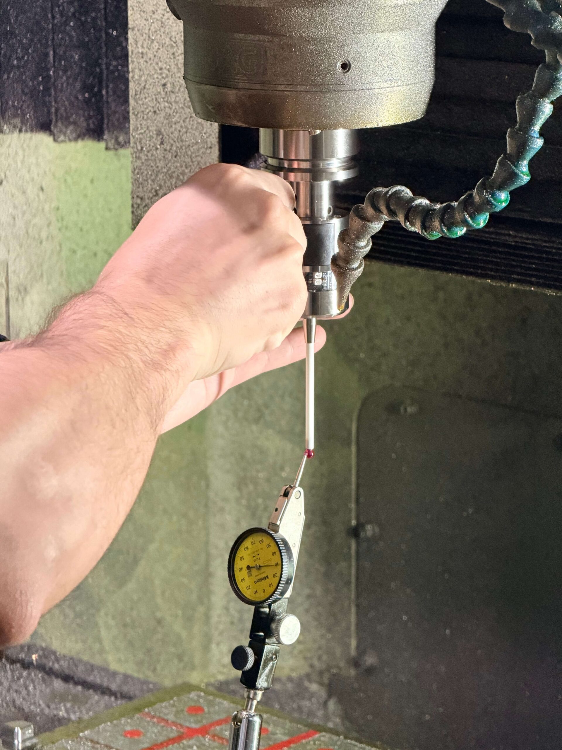
Place a dial test indicator against the stylus stem close to the ball, or at the contact position recommended by the cnc probe manufacturer.
Rotate the spindle slowly by hand through one complete revolution. Never run the spindle under power while the indicator is touching the stylus.
Observe the indicator and identify the highest and lowest readings. The difference between them is the total indicated runout.
The centering screws normally work in opposing pairs. Before tightening the screw that moves the cnc probe in the required direction, release the screw on the opposite side slightly.
Make very small changes.
After each adjustment:
- Rotate the spindle through another full revolution.
- Find the new high and low readings.
- Correct approximately half of the remaining error.
- Repeat the process.
Trying to remove the entire error with one adjustment often pushes the stylus past center, leaving you to correct it from the other direction.
Once the rough runout is acceptable, tighten the main mounting screws gradually and evenly. Do not fully tighten one screw while the others remain loose.
Measure the runout again after tightening. The probe body often moves slightly as the final torque is applied, so needing another fine-adjustment pass is completely normal.
The acceptable runout depends on the probe model and application. As one official example, the Renishaw OMP60 procedure calls for bringing the stylus-tip runout below 20 µm before final tightening and states that 5 µm should be achievable during final centering. Those values should not be copied automatically to a different probe; always use the specifications and torque values for the installed model.
Step 6: Test the Probe Under Real Machine Conditions
Activate the cnc probe from several machine positions and with the spindle at the orientation used by the probing cycles.
Watch for false triggers caused by:
- Machine vibration
- Coolant striking the stylus
- Loose stylus joints
- Optical interference
- Unstable radio communication
- Excessive acceleration
- An unsuitable probing feed
Do not immediately increase the trigger force or enable heavy filtering to hide the problem.
First inspect the stylus, shank mounting, receiver position, cables, machine vibration, and probing speed. Trigger-force adjustment should normally be treated as a last resort.
Changing the trigger force can affect the point at which the probe generates its signal. If it is changed, recalibrate the probe before returning it to production.
Step 7: Calibrate the Probe—Do Not Merely Touch It Off
Mechanical centering places the stylus close to the spindle axis. It does not tell the control the probe’s actual measuring dimensions.
A complete calibration normally establishes three values.
Probe length
The stylus touches a clean reference surface whose Z position is known.
The calibration cycle calculates the cnc probe’s effective length and stores it in the appropriate tool offset or calibration variable.
Enter the reference-surface height carefully. An incorrect value can create a measurement that repeats very well while remaining wrong every time.
XY stylus offset
Even after careful centering, the stylus may not sit exactly on the spindle centerline.
A calibration cycle inside a known bore can calculate the small remaining X and Y offsets. The probing software then compensates for them during later measurements.
Effective stylus-ball radius
The physical radius of the stylus ball is not necessarily the same as its effective measuring radius.
The trigger mechanism, stylus bending, probing feed, and measuring direction influence the position at which the probe signal is generated.
A calibrated ring gauge or known bore allows the probing software to calculate the effective radius. Depending on the probe and software, different calibration values may be stored for different directions.
Official spindle-probe calibration workflows commonly use a known Z reference together with a ring gauge or known internal feature to establish probe length, XY offset, and effective ball-radius values.
Use only the calibration macros intended for the machine’s control and probing software.
A macro number copied from another controller may perform a different operation—or may not provide protected movement at all.
Step 8: Check Repeatability Before Chasing Accuracy
Once calibration is complete, measure the same clean reference several times without changing the setup.
Record the readings instead of relying on the value that appears briefly on the control screen.
The first question is not whether the average result is exactly nominal. The first question is whether the measurements remain close together.
When the readings wander, look for:
- A loose stylus
- A loose probe shank
- Chips, coolant, or oil on the reference
- Low battery voltage
- Excessive probing speed
- Machine vibration
- Thermal movement
- A damaged stylus
- Unstable receiver communication
When the results repeat closely but disagree with the certified reference, the likely cause is different. Check the calibration data, entered nominal value, active stylus data, temperature, machine geometry, or calibration variables.
An offset can correct a stable bias. It cannot make an unstable measuring process reliable.
Step 9: Verify the CNC Probe in More Than One Direction
A correct Z measurement does not prove that the cnc probe is ready for accurate XY measurement.
Measure a known bore in both X and Y. Compare the calculated center position and measured diameter.
Where practical, repeat the measurement after unloading and reloading the probe from the tool magazine. You can also repeat it at different spindle orientations.
The pattern in the results often reveals the problem.
- A result that changes with spindle orientation may indicate stylus runout, poor shank seating, or directional behavior.
- Correct Z results with poor XY results may indicate centering, XY offset, or stylus-radius calibration problems.
- A stable size error may indicate an incorrect master value or effective-radius calibration.
- An error that mainly appears in one machine axis may involve machine geometry or axis-specific settings.
For demanding applications, compare the on-machine measurement with a calibrated artifact or independent inspection result.
The probe uses the CNC machine’s own axes to measure. It therefore cannot independently certify the accuracy of the machine that is positioning it.
Step 10: Run a Controlled Proving Cycle
Before releasing the CNCプローブ for production, run a simple test program containing:
- Probe activation
- A protected approach move
- A single-surface measurement
- A bore or boss measurement
- A tolerance check
- A safe retract
- Probe switch-off
Run the program in single block with reduced rapid and feed overrides.
Then test the failure logic.
In a safe and controlled way, move the reference slightly outside the permitted measurement window or simulate a missing feature. Confirm that the machine stops and displays a useful alarm.
It should not write a large correction and continue machining.
A probing program has not been fully tested until you know what it does when the setup is wrong.
Why Can a CNC Probe Repeat Perfectly but Still Be Wrong?
This is a common on-site complaint:
“The cnc probe repeats within a micron, but the measured size is still incorrect.”
That normally means the probe trigger is stable, but the relationship between the probe, calibration reference, and machine is wrong.
Typical causes include:
- The ring-gauge value was entered incorrectly
- A chip was present during calibration
- The wrong stylus calibration set is active
- The probe was calibrated cold and used after the machine warmed up
- The spindle taper or shank was dirty
- The stylus was changed without recalibration
- Calibration and measurement used different probing feeds
- The machine has backlash or geometric error
Do not edit the result merely to make it match the expected number.
Find the source of the bias. A correction that appears to work on one feature may create a new error when the probe measures another direction or diameter.
Common On-Site Problems
The CNC probe triggers while moving through free space
Check vibration, loose stylus joints, coolant impact, damaged sealing components, receiver interference, and filtering settings.
Reducing the probing feed can help diagnose the issue, but it should not be used to hide a mechanical problem.
Results change after the probe is removed and reloaded
Clean the spindle taper and shank. Inspect the pull stud, holder seating, spindle orientation, and toolchanger handling.
Repeat the unload-and-reload test before modifying any calibration values.
Z measurement is good, but X and Y are poor
Recheck stylus runout, XY offset calibration, effective-radius calibration, and the ring gauge.
Also confirm that the stylus is not longer than necessary.
Results are stable but always oversized or undersized
Review the master size, units, active calibration variables, スタイラス data, probing direction, and reference temperature.
Accuracy becomes worse during the shift
Suspect thermal change before touching the centering screws.
Compare cold and warm measurements and review the machine’s warm-up routine.
Manual probing works, but the automatic cycle fails
Check the activation M-code, receiver visibility, timeout setting, protected-positioning macros, active plane, tool compensation, and work offset.
A manual stylus touch proves that the probe can trigger. It does not prove that the automatic program is correct or safe.
Before Leaving the Site
Confirm that:
- The probe is physically secure
- Stylus runout meets the model requirement
- All screws are tightened to the specified torque
- Communication works throughout the required machine volume
- Probe length has been calibrated
- XY offset has been calibrated
- Effective stylus radius has been calibrated
- Repeated measurements are stable
- A known feature measures within the agreed process limit
- Toolchange and spindle-orientation tests have passed
- Over-tolerance and alarm behavior has been tested
Record the calibration values and final verification results.
That record matters. If performance changes later, the operator or service engineer will have a reliable baseline for comparison. Contact 奇数計測 if you have any query.
