
Ein Laser-Werkzeugmessgerät ermöglicht eine schnelle, berührungslose und leicht zu automatisierende Werkzeugvermessung. Es kann jedoch auch ein trügerisches Gefühl der Sicherheit vermitteln: Ein Zyklus wird abgeschlossen, ein Versatz wird gespeichert, und die Maschine fährt fort. Wenn die Messwerte zu driften beginnen, von Zyklus zu Zyklus schwanken oder ein intaktes Werkzeug als defekt melden, besteht die richtige Vorgehensweise nicht darin, es immer wieder zu versuchen, bis ein Wert akzeptabel erscheint.
Behandeln Sie einen unregelmäßigen Messwert als Prozesssignal. Das Lasersystem, das Werkzeug, die Spindel, die Luftzufuhr, das CNC-Makro und das Maschinenkoordinatensystem beeinflussen das Ergebnis. Eine systematische Überprüfung hilft dabei, ein vorübergehendes Umgebungsproblem von einem wiederkehrenden Maschinen- oder Programmproblem zu unterscheiden, bevor es zu einem Ausschussteil, einem beschädigten Werkzeug oder einem unnötigen Ersatzkauf kommt.
In diesem Leitfaden wird erläutert, welche Überprüfungen zuerst durchgeführt werden sollten, welche Nachweise zu sammeln sind und wann der Maschinenhersteller oder der Lieferant der Laserbearbeitungsmaschine hinzugezogen werden sollte.
Erstens: Definieren Sie, was “inkonsistent” bedeutet
Bevor Sie irgendetwas einstellen, sollten Sie das Symptom genau dokumentieren. Hinter der Aussage “Der Laser ist ungenau” können sich mehrere verschiedene Probleme verbergen:
- Die gemessene Werkzeuglänge ändert sich, wenn dasselbe Werkzeug wiederholt geprüft wird.
- Die Durchmesser- oder Radiuswerte weichen stärker ab, als es der Prozess zulässt.
- Ein Zyklus zur Erkennung defekter Werkzeuge löst gelegentlich einen Fehlalarm aus.
- Das System misst ein Werkzeug zuverlässig, hat jedoch Schwierigkeiten mit bestimmten kleinen, beschichteten, reflektierenden, geriffelten oder unregelmäßig geformten Werkzeugen.
- Die Messwerte ändern sich erst nach einer Bearbeitung mit hohem Kühlmittelverbrauch, einem Werkzeugwechsel, einer Aufwärmphase oder einer Wartungsmaßnahme.
- Der Messwert ist stabil, aber das bearbeitete Merkmal ist fehlerhaft. In diesem Fall kann die Ursache in der Offset-Konvention, der Werkzeuggeometrie, dem Rundlauf, dem Zustand der Spindel, dem Werkstück-Offset oder dem Zerspanungsprozess liegen – nicht in der Lasermessung selbst.
Notieren Sie das aktuell ausgeführte Programm, die Werkzeugnummer, den Messwert, die vorgegebene Messrichtung, den Spindelstatus, den Kühlmittelstatus sowie den Zeitpunkt der Beobachtung. Erfassen Sie mehrere Messwerte unter denselben kontrollierten Bedingungen. Ein einzelner Messwert ist selten ein Hinweis auf einen Fehler; ein wiederkehrendes Muster ist für die Personen, die die Fehlerursache ermitteln müssen, weitaus hilfreicher.
Wie ein Laser Einrichter für Werkzeugmaschinen erreicht einen Messwert
Die meisten berührungslosen Laser-Werkzeugmessgeräte arbeiten als optische Barriere. Ein Sender sendet einen Strahl an einen Empfänger. Wenn das Werkzeug den Strahl ausreichend unterbricht, sendet das System ein Trigger- oder Überspringsignal an die CNC-Steuerung. Die Steuerung erfasst bei diesem Ereignis ihre Achsposition und berechnet anhand des Messzyklus eine Länge, einen Durchmesser, einen Wert zum Rundlauf oder das Ergebnis eines Werkzeugbruchs.
Diese einfache Beschreibung verdeutlicht, warum zuverlässige Ergebnisse nicht allein vom Sensor abhängen. Der Auslösepunkt kann durch Verunreinigungen im Strahlengang, die tatsächliche Position und Form des rotierenden Werkzeugs, die Annäherungsrichtung und -geschwindigkeit, die Signalverarbeitung sowie die Interpretation der Maschinenposition durch das Makro beeinflusst werden. Führende Anbieter von Messtechnik beschreiben Lasersysteme als eine Kombination aus berührungsloser Werkzeugvermessung und -überwachung; sie betonen zudem den Schutz vor Kühlmittel und Spänen. Übersicht über die CNC-Laser-Werkzeugmessgeräte von Renishaw und BLUM – LaserControl im Überblick sind nützliche Hintergrundinformationen.
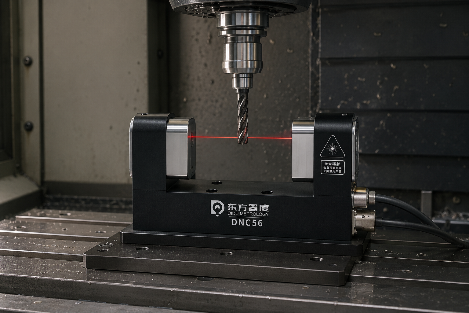
1. Überprüfen Sie den Strahlengang, bevor Sie die Offsets ändern.
Kühlmittelnebel, Späne, getrocknete Rückstände und Öl in der Luft können das Licht zwischen Sender und Empfänger teilweise blockieren oder streuen. Dies kann zu einer Verschiebung des scheinbaren Auslösepunkts oder zu einer unregelmäßigen Erkennung führen. Dies ist insbesondere nach aggressiver Schruppbearbeitung, Nassbearbeitung oder langen, unbeaufsichtigten Zyklen von Bedeutung.
Nachdem die Maschine gesichert wurde und unter Beachtung der Betriebsanleitung:
- Überprüfen Sie die Sender- und Empfängerfenster auf Rückstände, Beschädigungen oder lose Schutzvorrichtungen.
- Reinigen Sie das Gerät ausschließlich mit den zugelassenen Materialien und nach der vorgeschriebenen Methode. Scheuernde Reinigungstücher, nicht zugelassene Lösungsmittel und selbstgebastelte Werkzeuge können optische Oberflächen oder Dichtungen beschädigen.
- Prüfen Sie, ob sich aufgrund der Düsenausrichtung, der Geometrie des Gehäuses oder einer fehlenden Abdeckung Späne im Bereich der Messzone ansammeln können.
- Vergewissern Sie sich, dass sich Klappen, Abdeckungen oder Schutzvorrichtungen vollständig bewegen lassen, sofern das installierte Modell über solche verfügt.
- Führen Sie dieselbe kontrollierte Messung nach der Reinigung erneut durch und vergleichen Sie die aufgezeichneten Werte.
“Beheben” Sie ein Verunreinigungsproblem nicht durch einen Werkzeugversatz. Wenn durch die Reinigung die Wiederholgenauigkeit wiederhergestellt wird, dokumentieren Sie den Zustand und nehmen Sie einen praktischen Prüfpunkt in den Wartungsplan der Maschine auf.
2. Achten Sie auf saubere, trockene Schutzluft, nicht nur auf den Luftdruck
Viele Laseranlagen nutzen Luft, um Kühlmittel und Fremdkörper aus dem Strahlengang fernzuhalten und in manchen Fällen das Werkzeug vor der Messung zu reinigen. Ein Manometer allein reicht nicht aus, um zu belegen, dass diese Funktion einwandfrei arbeitet. Wasser, Öl, verstopfte Filter, undichte Anschlüsse, eine falsche Ventilsteuerung oder eine verstopfte Düse können den Schutz beeinträchtigen, selbst wenn der Versorgungsdruck normal erscheint.
Vergleichen Sie die Installation mit dem aktuellen Handbuch und der pneumatischen Zeichnung:
- Ist die Luftzufuhr aktiviert, wenn der Messzyklus läuft?
- Werden Filter, Trockner und Ablassstellen termingerecht gewartet?
- Erreicht die Luft sichtbar den gewünschten Bereich, ohne dass Späne zurück in den Strahl geblasen werden?
- Sind die Schläuche geknickt, rissig, verschmutzt oder gelöst?
- Stimmt die Logik der Zusatzluftversorgung der Maschine mit der Makrosequenz überein?
Ändern Sie niemals die Druckeinstellungen und umgehen Sie niemals Sicherheitsverriegelungen auf der Grundlage eines allgemeinen Artikels. Der richtige Wert und der richtige Zeitpunkt sind anlagenspezifisch. Ein Techniker sollte sich an die Spezifikationen des Lieferanten und die Dokumentation des Maschinenherstellers halten.
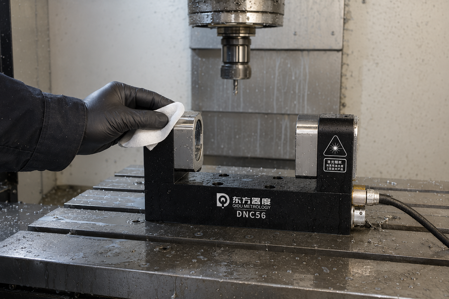
3. Den Zustand von Werkzeug und Halter ausschließen
Der Laser misst das tatsächlich in der Spindel befindliche Werkzeug und nicht die ideale Werkzeuggeometrie aus der CAM-Bibliothek. Eine abgeplatzte Kante, anhaftendes Material, ein dicker Kühlmittelfilm, ein verbogenes Mikrowerkzeug, eine lockere Spannzange, Verunreinigungen im Konus oder ein übermäßiger Werkzeugüberstand können das Bild, das der Laserstrahl erfasst, verändern.
Beginnen Sie mit einer bekanntermaßen einwandfreien Werkzeug- und Halterbaugruppe. Prüfen Sie diese gegebenenfalls außerhalb der Maschine und wiederholen Sie anschließend einen einfachen Messzyklus. Wenn das Ergebnis mit der Referenzbaugruppe stabil ist, mit einem Serienwerkzeug jedoch nicht, sollten Sie sich zunächst auf das Schneidwerkzeug, die Spannvorrichtung und die Werkzeugdaten konzentrieren, bevor Sie das Lasersystem als fehlerhaft einstufen.
Bei rotierenden Prüfungen ist besonders auf den Rundlauf zu achten. Der Rundlauf des Werkzeugs kann das vom Strahl wahrgenommene effektive Profil und das Schnittergebnis beeinflussen. Die entscheidende Frage ist nicht, ob ein einzelner angezeigter Durchmesser mit einem Nennwert aus dem Katalog übereinstimmt, sondern ob die Messmethode und die Toleranz für die tatsächliche Werkzeuggeometrie und die Bearbeitungsanforderungen geeignet sind.
4. Die Messbedingungen wiederholbar halten
Die Messergebnisse können sich ändern, wenn sich die Zyklusbedingungen ändern. Vergleichen Sie Gleiches mit Gleichem:
- Verwenden Sie dieselbe Anflugrichtung und denselben vorgesehenen Messpunkt.
- Verwenden Sie beim Testen dieselbe Zuführung und dieselbe Makro-Option. Ändern Sie nicht gleichzeitig die Zuführung, die Überspringlogik und die Offset-Logik.
- Erfassen Sie, ob die Spindel stillsteht oder sich dreht und mit welcher Sollgeschwindigkeit.
- Halten Sie den Zustand des Kühlmittels und der Luft während des Tests konstant.
- Wenn thermische Ausdehnung als möglicher Faktor in Betracht kommt, sollten die gleichen Aufwärmbedingungen gelten.
Berührungslose Systeme können Werkzeuge während der Drehung prüfen, doch die geeignete Vorgehensweise hängt von der Werkzeugform, der Drehzahl, der installierten Hardware und dem Makro ab. So erklärt Marposs beispielsweise, dass Lasersysteme Durchmesser und Länge messen und den Rundlauf bei Arbeitsdrehzahl überwachen können, während in der separaten Erörterung zur Mikrobearbeitung darauf hingewiesen wird, dass sehr kleine oder ungewöhnliche Geometrien eine sorgfältige Auswahl der Methode erfordern. Laser-Werkzeugvermessungstechnologie von Marposs ist eine hilfreiche Anleitung zu diesem Prinzip.
5. Überprüfung der Makro- und Offset-Konvention
Wenn der Messwert reproduzierbar erscheint, der Schnitt jedoch falsch ist, überprüfen Sie die Programmlogik. Selbst ein korrekter Lasertrigger kann zu einem falschen Ergebnis führen, wenn das Makro den falschen Versatz schreibt, auf den falschen Masterwert verweist, das falsche Vorzeichen anwendet, eine falsche Werkzeugnummer verwendet oder Geometrie- und Verschleißversätze unerwartet miteinander vermischt.
Stellen Sie folgende Fragen:
- Welche Makro-Version ist aktiv, und ist sie für diesen Controller und dieses Lasersystem zugelassen?
- Welcher Speicherort der Offset-Tabelle wird geschrieben, und handelt es sich dabei um die vom Produktionsprogramm verwendete Tabelle?
- Welches Bezugselement, welche Referenzmaß oder welchen Bezugspunkt geht der Zyklus voraus?
- Unterscheidet das Programm zwischen Ersteinrichtung, Werkzeugwechsel, Verschleißaktualisierung und Bruchprüfung?
- Hat jemand seit dem letzten bekanntermaßen fehlerfreien Ergebnis ein geschütztes Makro, einen Maschinenparameter oder eine SPS-Schnittstelle bearbeitet?
Sichern Sie die Steuerungsdaten gemäß den Anweisungen des Maschinenherstellers, bevor Sie eine genehmigte Änderung vornehmen. Kopieren Sie niemals ein Makro von einer anderen Maschine, nur weil die Steuerungsfamilie ähnlich ist; elektrische Schnittstellen, Maschinenkinematik, Sicherheitslogik und Parameterkonventionen können sich unterscheiden.
6. Maschinenbewegung und Spindelzustand überprüfen
Bei der Lasermessung ist es entscheidend, dass die CNC-Steuerung zum Zeitpunkt der Auslösung eine aussagekräftige Maschinenposition erfasst. Spiel, Probleme mit den Achsenservos, lockere mechanische Komponenten, eine ungleichmäßige Spindelausrichtung, thermische Bewegungen und Kollisionsschäden können daher als Problem bei der Werkzeugeinstellung erscheinen.
Verwenden Sie die Diagnoseroutine des Maschinenherstellers und ein geeignetes Referenzwerkstück oder -werkzeug, um festzustellen, ob die Abweichung auf eine Achse, den Spindelzustand, einen Werkzeugwechsel oder die Temperatur zurückzuführen ist. Wenn die Abweichung auch dann bestehen bleibt, wenn Sie unter kontrollierten Bedingungen ein bekanntermaßen einwandfreies Referenzwerkzeug messen, sollten Sie die Werkzeugkorrekturen nicht weiter anpassen. Leiten Sie den Fall unter Beifügung des Messprotokolls, des Alarmverlaufs und der Diagnoseergebnisse der Maschine an die nächste Instanz weiter.
7. Die Erkennung defekter Werkzeuge als eigenständige Funktion testen
Für die Längeneinstellung, die Durchmessermessung und die Brucherkennung können unterschiedliche Zykluslogiken und Akzeptanzgrenzen zum Einsatz kommen. Ein zuverlässiger Zyklus zur Längeneinstellung ist kein automatischer Beweis dafür, dass eine Hochgeschwindigkeits-Bruchprüfung korrekt konfiguriert ist.
Bei einem falschen Alarm wegen eines Werkzeugbruchs überprüfen Sie die erwartete Werkzeuglänge, die Zielposition, den Sicherheitsabstand, die Messrichtung und den Entscheidungsschwellenwert des Programms. Bei einer verpassten Erkennung sollten Sie den Zyklus nicht weiter ausführen, bis die Ursache von qualifiziertem Personal untersucht wurde. Die mögliche Folge ist, dass ein Werkzeug weiter schneidet, obwohl es hätte entfernt werden müssen; daher handelt es sich hierbei nicht um einen Parameter, der leichtfertig gelockert werden sollte, um Fehlalarme zu vermeiden.
Eine kontrollierte Überprüfungssequenz
Führen Sie diese kurze Abfolge nach jeder genehmigten Reinigungs- oder Wartungsmaßnahme durch:
- Sorgen Sie für die Sicherheit der Maschine; überprüfen Sie, ob das richtige Programm und das richtige Werkzeug ausgewählt sind.
- Den Strahlengang überprüfen und, sofern zulässig, reinigen sowie die Betriebsbereitschaft der Schutzgasversorgung bestätigen.
- Setzen Sie ein bekanntermaßen einwandfreies Referenzwerkzeug und eine Referenzhalterung ein.
- Verwenden Sie einen zugelassenen Messzyklus mit festen Bedingungen für Annäherung, Vorschub, Spindel und Kühlmittel.
- Führen Sie wiederholte Messungen durch und notieren Sie jedes Ergebnis, anstatt den bevorzugten Wert auszuwählen.
- Vergleichen Sie die Streuung mit den Prozessanforderungen und der vom Lieferanten angegebenen Leistungsfähigkeit für die installierte Konfiguration.
- Wenn alles stabil läuft, wiederholen Sie den Vorgang mit dem betroffenen Produktionswerkzeug.
- Wenn das Problem auf das Werkzeug zurückzuführen ist, überprüfen Sie das Werkzeug bzw. den Halter und die zugehörigen Daten. Wenn es auf die Maschine oder den Arbeitszyklus zurückzuführen ist, sichern Sie die Beweise und leiten Sie die Angelegenheit weiter.
Diese Abfolge dient nicht der Zertifizierung des Systems. Sie schafft eine klare Ausgangsbasis für die Bewertung durch einen Anwendungsingenieur, ein Wartungsteam oder einen Lieferanten.
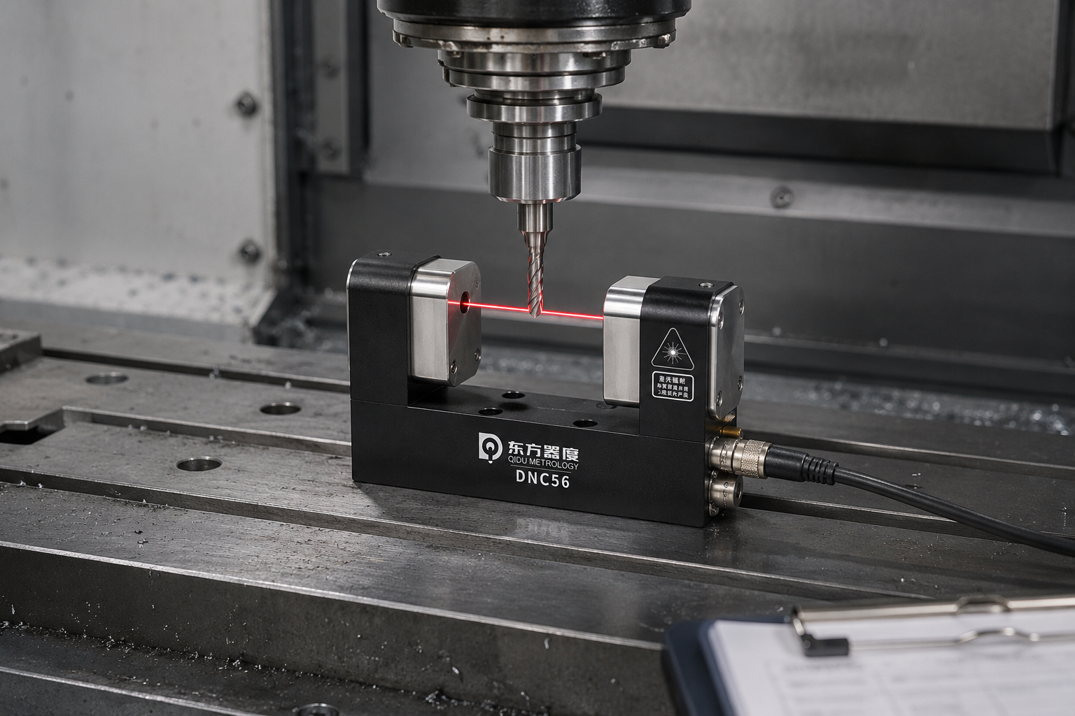
Wenn ein Laser-Werkzeugmessgerät möglicherweise nicht die ideale Lösung ist
Ein Laser-Werkzeugmessgerät ist besonders dann sinnvoll, wenn eine berührungslose, schnelle Werkzeugvermessung und -überwachung einen Mehrwert bietet. Es ist kein universeller Ersatz für jede Prüf Aufgabe. Extrem kleine Werkzeuge, transparente oder ungewöhnliche Schneidformen, starke Kühlmittelverunreinigungen, spezielle Schleifwerkzeuge oder die Notwendigkeit, Merkmale zu prüfen, die mit optischen Verfahren nicht praktikabel sind, erfordern möglicherweise eine andere Strategie, zusätzliche Kontrollen oder eine andere Messtechnik.
Das ist eine Frage der Auswahl und des Einsatzes, kein Defekt der Maschine. Hexagon beispielsweise positioniert Laser-Werkzeugmessgeräte zur berührungslosen Werkzeugvermessung und zur automatischen Überprüfung auf Verschleiß oder Bruch; in den Produktinformationen werden zudem Einschränkungen hinsichtlich Werkzeuggröße und Montage hervorgehoben, die auf die jeweilige Anwendung abgestimmt werden müssen. Das Sortiment an Laser-Werkzeugmessgeräten von Hexagon bietet eine nützliche Orientierungshilfe für Käufer.
Geben Sie dem Lieferanten für ein neues Projekt das Steuerungsmodell, den Maschinenaufbau, den Spindelbereich, den Werkzeugdurchmesserbereich, die Kühlmittelart, die vorgesehenen Zyklen, die erforderliche Toleranz, den Produktionsmix und den Automatisierungsplan an. Die beste Lösung für die Werkzeugeinstellung ist diejenige, deren Messverfahren, Umweltschutzmaßnahmen, Makros und Supportprozesse alle auf den jeweiligen Anwendungsfall zugeschnitten sind.
Ein praktisches Eskalationspaket
Wenn Sie sich an Qidu Metrology, den Maschinenhersteller oder einen Servicepartner wenden, fügen Sie bitte Unterlagen bei, anhand derer das technische Team die Problemstellung nachvollziehen kann:
- Maschinenmarke/-modell, Steuerung und Spindeltyp
- Modell und Seriennummer des Laser-Werkzeugmessgeräts
- Angaben zu Werkzeug und Halter, einschließlich Nenngeometrie und Zustand
- Der Name des betroffenen Makros oder Zyklus sowie relevante, unbedenkliche Auszüge
- Messprotokolle vor und nach der Reinigung oder Wartung
- Alarmverlauf, Fotos des optischen Bereichs und, sofern dies gefahrlos möglich ist, ein kurzes Video des Zyklus
- Kühlmittel, Luftschutz und Spindelzustände während des Tests
- Das Datum, an dem das Symptom zum ersten Mal auftrat, sowie etwaige zuvor vorgenommene Änderungen
Das spart Zeit und verhindert Spekulationen. Außerdem ermöglicht es eine fachlich fundierte Entscheidung hinsichtlich Reinigung, Reparatur, Programmüberprüfung oder Geräteauswahl.
