
Un sistema de ajuste de herramientas puede estar instalado mecánicamente, alimentado y activarse de forma visible, y aun así no estar listo para proteger un ciclo de producción. Lo que suele faltar es la puesta en marcha: comprobar que el dispositivo físico, la señal eléctrica, la lógica del CNC y los datos de herramientas almacenados concuerden entre sí.
Esa distinción es importante. Un programador de herramientas establece las dimensiones de las herramientas y los datos de estado para el control; a continuación, el control utiliza esos datos en los ciclos de compensación de herramientas y de mecanizado. Si la referencia de montaje, la entrada del disparador, las variables de macro o el proceso de punto de referencia son incorrectos, un disparador aparentemente normal puede seguir produciendo una compensación incorrecta. El resultado puede ser un corte en vacío, un sobrecorte, un ajustador de herramientas dañado o una pieza no conforme.
Esta lista de comprobación está pensada para un sistema fijo de tipo contacto Ajustador de herramientas CNC en un centro de mecanizado. También resulta útil a la hora de recibir un sistema instalado por un fabricante de máquinas o un integrador. No sustituye al manual de la máquina-herramienta, al manual del control CNC, a las instrucciones de instalación del ajustador de herramientas ni a los procedimientos de seguridad de su centro de trabajo. Pida a un técnico cualificado que revise los ajustes finales antes de iniciar la producción.
Empieza por establecer un objetivo de aceptación claro
Antes de modificar los parámetros, decide qué significa “listo” para esta máquina en concreto. Anota:
- el modelo de la máquina, el sistema de control y la versión del software o de las macros;
- el modelo del ajustador de herramientas, el tipo de salida y la revisión del esquema de cableado;
- las tareas de ajuste de herramientas que se van a realizar (por ejemplo, ajuste de longitud, ajuste de diámetro o comprobación de herramientas rotas);
- la herramienta de referencia o el artefacto certificado utilizado para la verificación;
- las herramientas, los soportes, las velocidades y las direcciones de aproximación previstas; y
- que puedan modificar los parámetros protegidos, la lógica PMC/PLC o las macros de sondeo.
Este registro resulta más útil que una etiqueta genérica de «aprobado/suspendido». Establece un punto de referencia trazable para la resolución de problemas en el futuro tras un fallo, la sustitución del lápiz óptico o la almohadilla, el mantenimiento del equipo o un cambio de software.
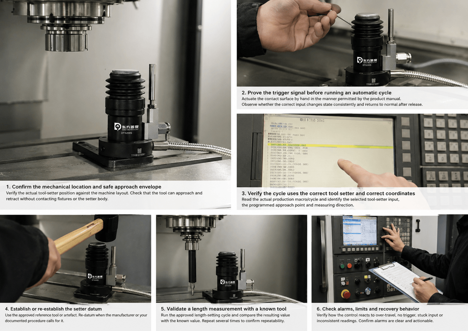
1. Confirmar la ubicación mecánica y el espacio de maniobra seguro
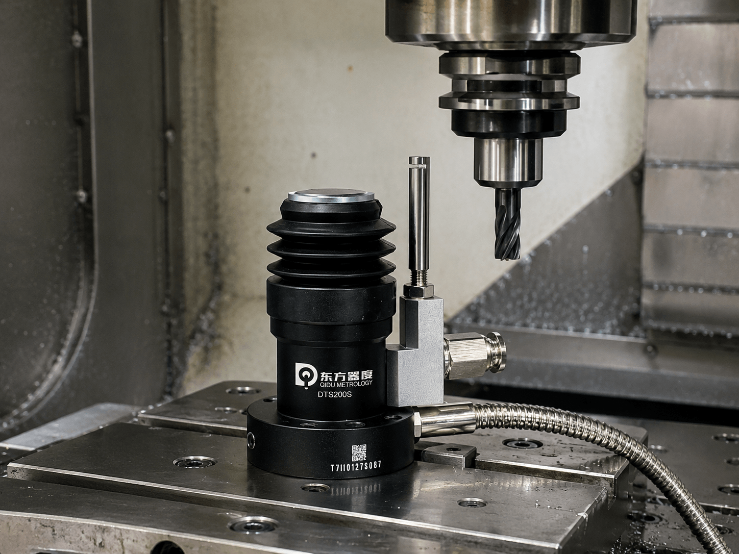
Comprueba la posición real del dispositivo de ajuste de herramientas con respecto a la disposición de la máquina, no solo con respecto al plano. Normalmente, un dispositivo de ajuste de herramientas por contacto se monta en la mesa o en la estructura de la máquina; su posición medida debe coincidir con las coordenadas utilizadas por el ciclo.
Comprueba que la herramienta pueda acercarse y retirarse sin entrar en contacto con los elementos de sujeción, las abrazaderas, los componentes del palé, las protecciones o el cuerpo del colocador. Incluye en esta comprobación la herramienta más larga, la de mayor diámetro y el espacio libre del cambiador de herramientas. Si la máquina utiliza un eje giratorio, comprueba también las orientaciones pertinentes.
Comprueba también las fijaciones, la protección de los cables y la exposición a virutas y líquido refrigerante. No des por sentado que un grado de protección elimina la necesidad de un tendido adecuado y una limpieza correcta. El objetivo es sencillo: durante cada ciclo permitido, solo debe entrar en contacto la superficie de contacto prevista.
2. Comprueba la señal de activación antes de iniciar un ciclo automático
Utilice los diagnósticos del controlador o la pantalla de E/S homologada por el fabricante de la máquina para comprobar los estados normal y activado de la entrada. Con la máquina en condiciones seguras, accione la superficie de contacto manualmente y únicamente de la forma permitida en el manual del producto. Observe si la entrada correspondiente cambia de estado de forma coherente y vuelve al estado normal tras soltarla.
A continuación, comprueba los detalles que se suelen pasar por alto:
- dirección de entrada y polaridad de la señal;
- expectativa de «normalmente abierto»/«normalmente cerrado» en la lógica de control;
- estado del apantallamiento del cable, del conector y del alivio de tracción;
- que no se produzca ningún estado intermitente cuando se desplacen los cables o los ejes de la máquina dentro del rango autorizado; y
- cualquier comportamiento de las luces indicadoras especificado por el fabricante.
No omitas ninguna entrada ni modifiques la lógica de la máquina relacionada con la seguridad con el único fin de que la pantalla se vea correcta. Si el estado que se muestra difiere de la documentación de cableado, detén la máquina y resuelve el problema con el fabricante de la máquina o con un técnico cualificado en sistemas de control.
3. Comprueba que el ciclo utilice el ajustador de herramientas y las coordenadas correctas
Una señal de E/S puede ser correcta aunque la macro llame al registro de entrada, de coordenadas, de desplazamiento o a la unidad equivocados. Lee la macro o el ciclo de producción actual —no una copia impresa antigua— e identifica:
- la entrada del sistema de ajuste de herramientas seleccionada;
- el punto de aproximación programado y la dirección de medición;
- las posiciones de arranque seguro y de retracción;
- la tabla de desplazamientos y los números variables generados por el ciclo;
- el sistema de unidades; y
- el comportamiento de la alarma o de recuperación tras una activación inesperada o en ausencia de activación.
Siempre que sea posible, realice una prueba en seco sobre el ajustador de herramientas con el husillo parado, avance reducido y control de un solo bloque, siguiendo las instrucciones del fabricante de la máquina. Una prueba en seco no puede validar la medición final, pero puede detectar una dirección incorrecta, una aproximación insegura o una trayectoria de macro inesperada antes de que se produzca el contacto.
4. Establecer o restablecer el punto de referencia de ajuste
El control debe conocer la relación entre el sistema de coordenadas de la máquina y la superficie de contacto efectiva del dispositivo de ajuste de herramientas. Los fabricantes suelen referirse a esto como «datuming» o «calibración». El método exacto depende del dispositivo de ajuste, del paquete de macros y del control.
Utiliza la herramienta de referencia o el artefacto homologado especificado por el fabricante de la máquina o en la documentación de la sonda. Anota su identificación, sus dimensiones nominales, su estado y la fecha. Asegúrate de introducir el valor en las unidades previstas y regístralo.
Vuelve a establecer el punto de referencia cuando así lo indique el fabricante o tu procedimiento documentado; por ejemplo, tras la sustitución de la superficie de contacto o del palpador, una realineación mecánica, un posible daño o cualquier trabajo que pueda alterar la relación de referencia. Nunca copies un valor de punto de referencia de otra máquina simplemente porque el hardware parezca similar.
5. Verificar una medida de longitud con una herramienta de referencia
Elige una herramienta de referencia estable y claramente identificada. Ejecuta el ciclo de ajuste de longitud aprobado con la velocidad de avance especificada y compara el valor resultante con el valor conocido o con un método de medición independiente y controlado que se utilice en tu centro.
Repite el mismo proceso varias veces sin modificar la configuración. Lo que buscas es la repetibilidad en todo el sistema: herramienta, portaherramientas, husillo, dispositivo de ajuste, señal, movimiento y macro; no un único valor favorable. Si los resultados varían, investiga la causa antes de iniciar la producción. Entre los posibles factores que pueden influir se encuentran el asentamiento de la herramienta, la limpieza del portaherramientas, el estado del husillo, un montaje flojo, fallos en los cables, un método de aproximación incorrecto o una herramienta de referencia inadecuada.
Establece un límite de aceptación interno que se ajuste a la tolerancia de la pieza, a la capacidad del proceso y a tu plan de calidad. No publiques ni adoptes una única tolerancia universal: el límite adecuado depende de cada aplicación concreta.
6. Verifica que el método de medición sea adecuado para la geometría de la herramienta que vas a utilizar realmente
La longitud de la herramienta no lo es todo. Si el proceso establece el diámetro, el radio, el estado de rotura de la herramienta o una geometría especial, comprueba ese ciclo concreto con herramientas representativas.
Por ejemplo, una broca larga, una fresa pequeña, una fresa de cara plana y una fresa de punta esférica pueden requerir diferentes posiciones de aproximación o lógicas de medición. Comprueba que el punto de contacto programado de la herramienta sea físicamente válido y que la macro escriba la geometría o la compensación por desgaste previstas. En el caso de los sistemas láser sin contacto, utilice el procedimiento de gestión del haz, el refrigerante y el aire prescrito por el proveedor, en lugar de aplicar sin modificaciones una lista de comprobación para ajustadores de contacto.
Este es también el momento adecuado para comprobar cómo funciona la detección de herramientas rotas. Se trata de una comprobación definida con una referencia programada y una respuesta de alarma, pero no garantiza que se detecten todos los posibles defectos de corte.
7. Realiza una prueba controlada del primer artículo y, a continuación, comprueba el resultado fuera de la máquina.
Utilice una pieza de prueba o una primera pieza de producción, las medidas de seguridad adecuadas y condiciones de mecanizado de riesgo reducido. Ajuste las herramientas pertinentes siguiendo el proceso aprobado, mecanice una característica sensible a la desviación de la herramienta y, a continuación, inspeccione la pieza con el método de control de calidad habitual.
Compara el resultado medido con el valor de referencia programado y con el registro del ciclo de ajuste de la herramienta. De este modo se cierra el bucle entre los datos de la herramienta y la retirada real de metal. Una señal de E/S correcta por sí sola no basta para ello.
Si el resultado de la pieza es incorrecto, evita aplicar compensaciones a ciegas en la tabla de compensaciones. Primero, determina si el problema tiene su origen en la referencia de la herramienta, los datos de la herramienta, la compensación de la pieza, el programa, el dispositivo de sujeción, el estado de la máquina o el proceso de corte. Documentar la causa raíz evita que un cambio temporal en la compensación oculte un problema recurrente.
8. Fijar la línea de base y definir las comprobaciones rutinarias
Una vez aceptados, guarda los ajustes y los registros siguiendo el procedimiento de control de cambios de la máquina. Realiza capturas de pantalla o exporta los parámetros relevantes de la macro, siempre que esté permitido, además del informe de puesta en marcha, el resultado de la herramienta de referencia y la inspección del primer artículo.
Establece quién revisa el sistema de ajuste de herramientas y con qué frecuencia. Una rutina práctica puede incluir una inspección visual para detectar virutas o daños, la confirmación del estado de entrada previsto, la verificación periódica de la herramienta de referencia y un reinicio del punto de referencia tras determinados eventos de mantenimiento. El intervalo debe basarse en las instrucciones del fabricante de la máquina, el manual del sistema de ajuste de herramientas, la evaluación de riesgos y la experiencia en producción, y no en una cifra copiada de otro taller.
Una nota para Qidu DTS200 usuarios
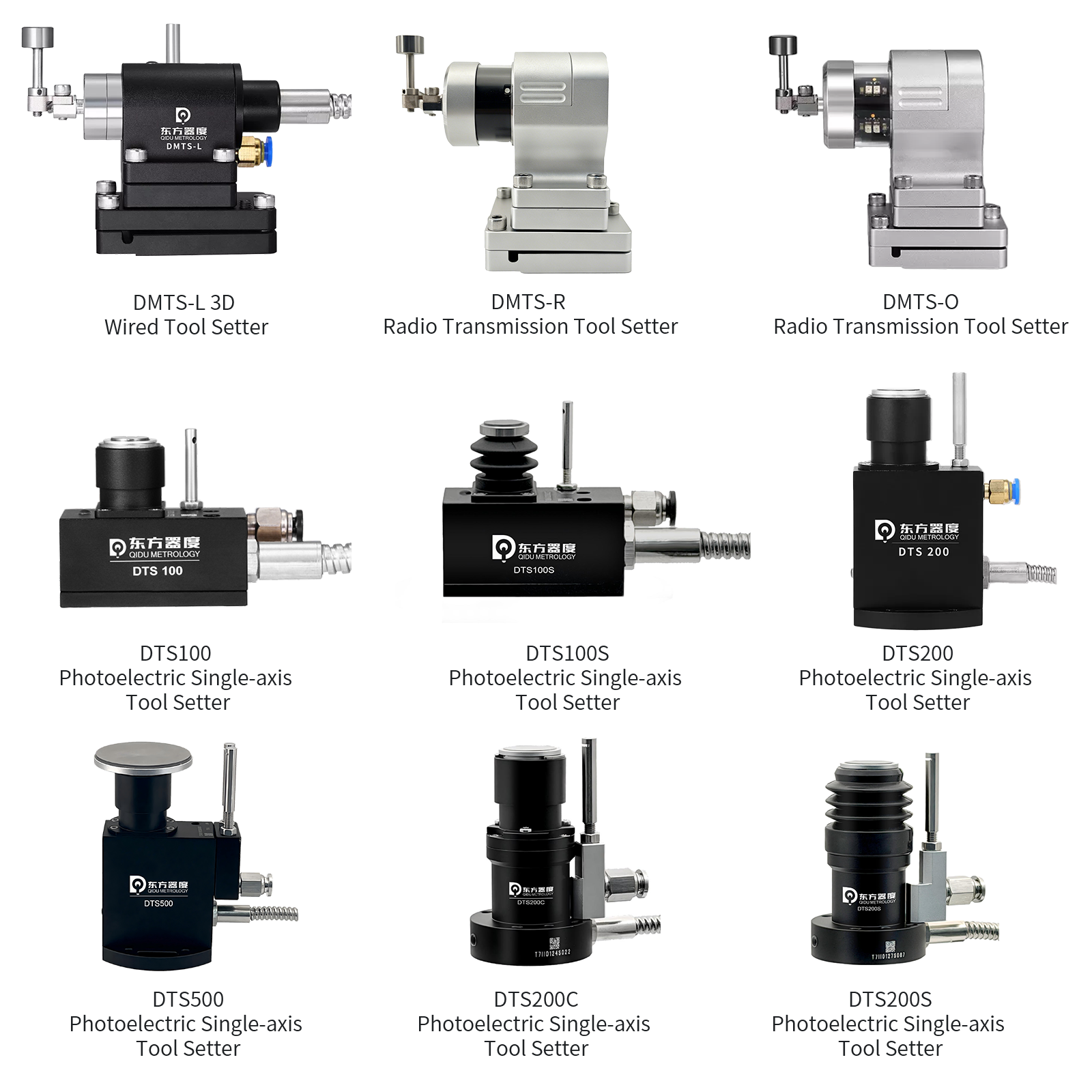
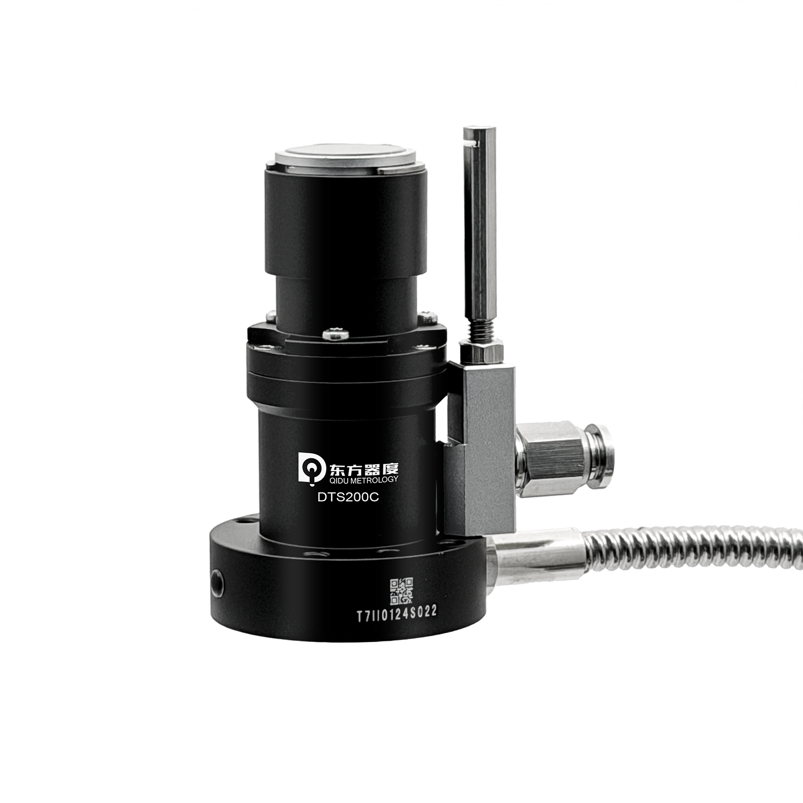
La página pública del DTS200 de Qidu describe un ajustador de herramientas con contacto +Z, conectado por cable, con una salida A/NO y una almohadilla de contacto de 20 mm. La página publicada también incluye información sobre las condiciones de repetibilidad de las pruebas, los parámetros eléctricos, la fuerza de activación y la protección. Esos detalles sí no Comprueba si es compatible con un control, una macro, una configuración de tensión o un entorno de máquina concretos. Confirma con el servicio de asistencia técnica de Qidu el consumo de corriente, el esquema de cableado, la revisión del modelo y el procedimiento de puesta en marcha homologado antes de la instalación o de realizar cambios en los parámetros.
Conclusión práctica
Un buen proceso de puesta en marcha sigue una secuencia: posición mecánica → señal de activación → ciclo CNC → punto de referencia → datos de compensación → pieza mecanizada. Si se da por sentado algún eslabón de la cadena en lugar de verificarlo, un ciclo automático de ajuste de herramientas puede generar una confianza infundada.
Para los fabricantes de maquinaria y los distribuidores, proporcionar un informe de puesta en marcha completo junto con el ajustador de herramientas es una forma práctica de aclarar el proceso de entrega. Para los equipos de mecanizado, esto convierte un nuevo dispositivo en un proceso controlado, en lugar de un accesorio sin verificar.
¿Necesitas ayuda para comprobar el ajuste del ajustador de herramientas, la información sobre el cableado o las especificaciones actuales de un modelo de Qidu? Ponte en contacto con Qidu Metrology junto con el modelo de la máquina, el control CNC, las tareas de ajuste de herramientas previstas y fotografías de la zona de instalación.
